

© 2020 - 2021 Keen Electronics Limited
e-mail: sales@keenelectronics.co.uk Telephone: 07500 24 11 33
127, New Road, Bromham, Chippenham, Wiltshire, SN15 2JA
Company Registration No: 2613501 VAT Registration No 596069885

Keen Electronics Limited


EARTH LEAKAGE SENSOR
Introduction
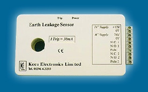
The Earth Leakage Sensor is designed to continuously monitor the unbalance current in a pair of load carrying conductors. These conductors pass through the aperture in the case, there is no electrical connection to be made. The sensor is well suited for use on circuits which are at voltages other than mains. Should the unbalance current reach 30mA the sensor will "trip", the relays will de-energise and the red LED will light.
- 30mA trip current - other values to order
- Two sets of Volt Free Relay contacts
- Fail safe relay operation
- 12 Volt d.c./24 Volt a.c. supply (24 Volt d.c to order)
- Small footprint is easy to install
Technical Specification
Unbalance (trip) - current 30mA
Operating frequency - 50 or 60Hz
Power requirements - 12 Volt d.c. or 24 Volt a.c
Current consumption - 70mA typical on 12 Volt d.c.
- 55mA typical on 24 Volt a.c.
Output 1 - SPCO contact rated 1.25A at 250V a.c.
Output 2 - SPCO contact rated 1.25A at 250V a.c.
Safety - Relays are energised in the SAFE state. Once a trip occurs both relays are de-energised and cannot be energised until the unbalance current is below the trip level and power to the unit has been switched off and then back on
Test Button (optional) - Operation of this button simulates a trip condition de-energising the relays and lighting the red TRIP LED
Power Indicator - Green LED is lit while power is applied
Trip Indicator - Red LED is lit when a trip occurs
Connections - 12 way rising clamp terminal block
Packaging - Mounted in a plastic case with mounting plates for back plate or chassis mounting
Size - 175 x 84 mm overall with fixing holes on 160 mm pitch
Installation Instructions
Mounting
The Earth Leakage Sensor should be mounted inside a metal enclosure using two M4 or similar bolts. The unit is not suitable for mounting in areas where water may get onto the unit.
Connections
- Pass the load carrying conductors through the hole in the case. Do not put an earth wire through this hole.
- Connect the supply to the appropriate terminals (12 Volt d.c. or 24 Volt a.c. - Note 24 Volt d.c. available to order)
- Connect the relay volt free contacts as required.
Operation
On application of the supply the green Power LED will light and both relays will energise.
Pressing the optional red Trip push button will trip the unit lighting the red Trip LED and both relays will de-energise. The supply must be switched off to reset the unit.
An unbalance in current in the load carrying conductors of 30mA or more, will trip the unit, lighting the red Trip LED and de-energising the relays.
Pricing
Please contact us by phone on 07500 24 11 33
or email sales@keenelectronics.co.uk