

© 2020 - 2021 Keen Electronics Limited
e-mail: sales@keenelectronics.co.uk Telephone: 07500 24 11 33
127, New Road, Bromham, Chippenham, Wiltshire, SN15 2JA
Company Registration No: 2613501 VAT Registration No 596069885

Keen Electronics Limited


INSTALLATION INSTRUCTIONS PROTECTOR TWO
INTRODUCTION
The alarm system consists of the following components: -
Control box – with internal re-chargeable PP3 battery and 12 way plug. The control box can be unplugged after installation for testing or fault finding. The control box should be mounted where a thief cannot easily get to it.
Key Fobs – carried by the user/s
Splash proof siren – this must be mounted where a thief cannot easily get to it. It is normally convenient to mount it close to the control box - over a grille in the floor, so the sound can get out and be heard outside the van When mounting over a grille in the floor ensure that the siren is a good fit, so that all of the sound goes through the floor and outside. (It’s no good making a lot of noise in the bed box!!)
PIR head – a ceiling mounting type is supplied for factory fitting. A wall mounting type for fitting to built caravans. Mount the PIR where it can detect intruders. Avoid fitting where it may pick up air currents from heaters.
Leg sensor - that should be fitted to the caravan floor adjacent to a rear steady. The magnet is fixed to the spindle so that rotation of the leg winder triggers the alarm.
INSTALLATION
Ensure that the 12Volt leisure battery is disconnected, the mains hook up is disconnected and the 13 pin plug is not plugged into a tow vehicle (or test box).
It’s well worth spending a few minutes deciding where to fit the alarm system’s components. Often wiring can be run at the back of bed boxes and cupboards, which saves drilling through the floor and working underneath the caravan. The wiring diagram shows how the system is connected.
Control box
Once the location has been decided screw the unit to the caravan floor or panel. Screw the terminal block to the caravan floor or panel so that the 12 way flying lead can be connected neatly between it and the socket on the control box.
Siren
Remove the mounting bracket fixing screws, and then screw the mounting bracket in the desired position. Re-fit the siren body into its mounting bracket and re-fit the fixing screws, ensure these are reasonably tight. Use the 2 way terminal block to connect the siren wires to the wires going to the control box. Fix the terminal block to the caravan with a single screw.
Ceiling mounting PIR Head
This should be mounted in a suitable location in the ceiling where an intruder will be detected. Avoid mounting the PIR head where it will be subject to air currents from heaters. Remove the lens cover using a wide flat bladed screwdriver in the groove that separates the two halves. Carefully remove the printed circuit board, which is secured by one screw. The PIR head is mounted using the pre-drilled holes in the base. Re-fit the printed circuit board and tighten the single screw. Connect the three wires from the control box as shown on the appropriate wiring diagram. Refit the lens cover and press to snap into place. NOTE – the lens cover has a small keyway so will only fit in one position.
Wall mounting PIR Head
This should be mounted at eye level “looking down” the caravan. Usual mounting positions are at the front of the caravan, on either side or in the centre. Avoid mounting the PIR head where it is directly facing a window. Remove the front half of the case by undoing the single screw, then carefully hinging it up and off. Carefully remove the printed circuit board, which is secured by one screw. The PIR head is mounted using the pre-drilled holes in the base. Re-fit the printed circuit board then slide it up/down until the scale on the right hand side is at position 2. Connect the 3 wires from the control box as shown on the appropriate wiring diagram. Refit the front half of the case and secure it with the fixing screw. (The PIR must be mounted with the terminal block at the top)
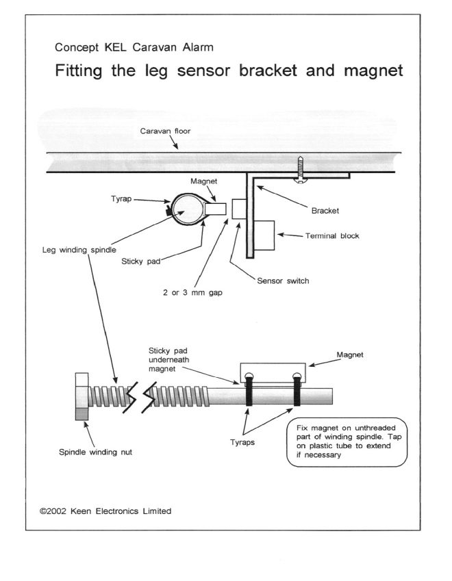
Leg Sensor
This should be fitted to a rear steady, with the magnet fixed to the "in board" end of the spindle and the bracket assembly mounted adjacent to it. Rotation of the leg winder should cause the magnet to pass within a couple of milli metres of the sensor fitted to the bracket. Please refer to the diagram.
Clean any grease off the spindle then stick the double-sided sticky pad onto the magnet, place the magnet onto the spindle then fix in place with the two cable ties. Tighten the cable ties with a pair of pliers - pull hard! Then cut off the surplus plastic from the cable ties.
Mount the bracket onto the underside of the caravan floor, positioned so that the magnet passes within a couple of milli metres of the sensor fitted to the bracket. Finally, connect the two wires from the leg sensor to the control box as shown in the wiring diagram.
ELECTRICAL CONNECTIONS
Please refer to the wiring diagram at the end of the text.
Connect the leg sensor to the control box using twin flat loudspeaker cable polarity is not important.
Connect the siren to the control box using twin flat loudspeaker cable, observe correct polarity - red siren wire to siren + and black siren wire to siren -.
Connect the PIR head to the control box using the 4-core cable supplied in the kit as shown in the wiring diagram. Please note that only 3 cores are used.
Locate a convenient point in the 13 pin wiring to connect to the BRAKE wire - usually red in colour.
Finally, connect the 12 Volt supply from the leisure battery to the control box. Do not use twin flat speaker cable, as it is rather thin for this application. A 0.75mm or 1.0mm cable (24/0.2) or similar is recommended. In some caravans it is practical to connect these wires via the battery charger, but in others it may be easier to connect direct to the leisure battery (always through a 2A in line fuse)
The alarm installation is now complete and ready for testing; ensure that the key switch is in the anti-clockwise (OFF) position. Then re-connect the leisure battery to test the alarm.
OPTIONAL LIGHT CONTROLLER
The button on the key fob marked LIGHT can be used to switch the awning light if required.
The wiring diagram shows how this should be connected.
IMPORTANT NOTE – the control box MUST be connected exactly as shown in the wiring diagram. The switch inside the control box is a transistor NOT a relay contact. If you cannot locate the negative return wire to break into then contact Keen Electronics who can supply you with a relay. This enables the positive feed wire from the awning light switch to be broken into and switched by the control box via the relay.
TESTING THE ALARM
With the key switch in the control box in the OFF position, check that the PIR detector flashes red when you move in front of it. (Note – when power is first applied there is a 2-minute “warm up” period when the PIR will not detect movement)
Now turn the key switch clockwise, the siren should “cheep” once.
NOTE – when pressing the ALARM or LIGHT buttons on the key fobs you need to press the buttons for a couple of seconds.
Press the ALARM button on the key fob to switch the alarm ON. The siren should cheep twice indicating the alarm is on.
Press the ALARM button a second time, the siren should cheep once indicating the alarm is OFF.
Now press the ALARM button, siren cheeps twice and alarm is ON. Now press both buttons together, siren sounds for 2 minutes, or until ALARM button is pressed again.
When the alarm is ON any one of the following actions should trigger the alarm sounding the siren instantly:-
Entering the caravan
Winding the “alarmed” rear steady
Hitching up and inserting the 13 pin plug
When hitched up removing the 13 pin plug
When hitched up with the 13 pin plug inserted, using the footbrake in the tow vehicle (ignition may need to be turned on)
Disconnecting the leisure battery. (The re-chargeable PP3 battery inside the control box is trickle charged by the leisure battery. When the alarm is first installed it can take 24 hours to charge.)
When the alarm is ON and the alarm is triggered the siren should sound for 2 minutes, unless switched OFF with the ALARM button on the key fob.
NOTE –once the alarm has been triggered the red LED on the control box will stop flashing regularly and will flash a certain number of times, pause, flash the same number of times, etc.
The Alarm Status table in the DIAGNOSTICS section of the Operating Instructions gives number of flashes for each sensor. The LED will continue flashing until the alarm has been reset with the key switch. The LED will revert to normal regular flashing when the alarm is next turned ON. Turning the alarm OFF will then stop the LED flashing. This feature is useful to advise the owners if the alarm has been triggered in their absence and for fault finding (especially intermittent false alarms).
DIAGNOSTICS
When the alarm is ON the status LED on the control box will flash once a second. When the alarm is turned OFF the status LED will go out.
If while the alarm is ON an alarm occurs, the siren will sound for 2 minutes and the status LED will flash a certain number of times, pause, flash the same number of times, pause, etc. The alarm can be turned OFF then back ON then OFF, but the LED will keep flashing. This enables the sensor which has triggered the alarm to be easily identified. To reset the status LED the small key is used to turn the control box off, then back on again. On turning the alarm back on with the key, the siren will “cheep” once and the LED will not flash.
Flash codes are :-
Regular flashes = Alarm ON
1 flash = Panic
2 flashes = Leg Sensor,
3 flashes = PIR,
4 flashes = 13 pin plug
5 flashes = Leisure Battery disconnected

FACTORY FITTED ALARM WIRING DIAGRAM
PLEASE NOTE !! WIRE COLOURS WILL BE DIFFERENT & TERMINAL BLOCK IS NOT USED
PLEASE REFER TO PLUG DIAGRAM AT THE BOTTOM OF THIS PAGE

RETAIL KIT WIRING DIAGRAM
